So, in a rush on Friday I claimed that the new LG TV I was reviewing delivered its 3D signal in a particular way. I should specify my method.
First: an assumption. Necessarily my tests were conducted by providing the TV with a 1080p 2D signal and then using it to convert to 3D, using the side-by-side 3D process, which is the process used with 3D TV broadcasts. This is fully explained here. The assumption is that the TV uses the same line allocation methods with other forms of 3D as it does with this one. So far I’ve seen nothing to make me think otherwise.
So here’s what I did: I created a number of 1,920 by 1,080 still images in which every single horizontal row of pixels was different to the row above. For example, here’s a detail of one called red-blue:
At first glance it looks like a solid purple block. But, in fact, it is a single row of red pixels, with a single row of blue pixels underneath, then a single row of red pixels and so on. Here’s a smaller detail of the same pattern, zoomed in to 300% to make it easier to see the row structure:
(I know
, I know, the red lines don’t look red, and the blue lines don’t look blue, but they are. I will post later to prove that your eyes are lying.)
With the TV set to 1:1 pixel mapping, each of those pixel rows occupies on scan line of the TV. When I showed this on the TV — in regular 2D mode — and donned the passive 3D glasses, the picture on the screen was entirely blue to my left eye, and entirely red to my right eye.
Since the top-most row of the test pattern was red, and if we count that row as #1, that means that the left eye sees the even (blue) rows, and the right eye sees the odd (red) rows.
What I also needed was a comparison test pattern. This one is identical to the first one, except that the line sequence is red, blue, red … only for the left half of it. On the right half it is reversed: blue, red, blue … Here is a detail, taken from the centre top of the actual pattern, and zoomed in for clarity:
Showing this pattern in regular 2D mode on the TV, and looking at it with the 3D glasses, to the left eye the left half of the screen is full blue (same as the first pattern), and (still with the left eye) the right half is full red (since the line sequence is reversed here). Through the right lens the left half of the screen is red, and the right half is blue.
Now here’s the thing: if we switch the TV to side-by-side 3D mode, the difference we see between these two test patterns will tell us what’s going on as far as which source lines are being used to create the output picture lines for the two eyes. If, for example, every odd line is discarded for both eyes, then we’d expect to see differences between the two different test patterns in 3D mode. Likewise if all the odd lines are discarded for one of the eyes and all the even ones for the other eye, then there must be differences between the two test patterns in 3D mode.
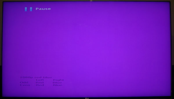
So what do we see? Well, here’s a photo of the screen of the TV showing the first test pattern. No glasses were used, so this is showing both left and right eye views simultaneously:
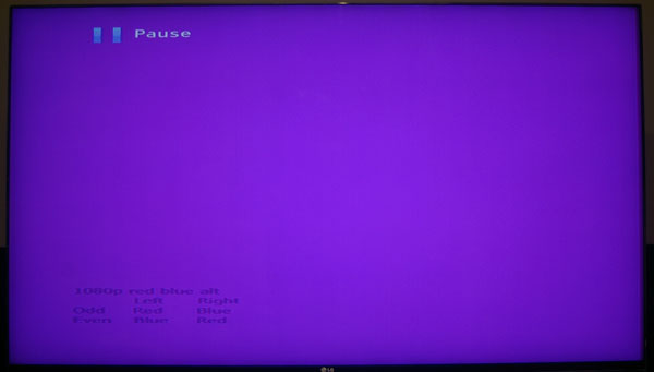
And here’s a photo under the same circumstances of the other test pattern (where the lines are reversed in the right hand view):
See any difference? Neither do I.
More importantly, there is no difference wearing 3D glasses. There is no difference between the left and right eye only views and these ones except for one thing: the ‘Pause’ and the text at the bottom right left were visible only in the left eye view since they came from the left hand part of the source. There are no differences regardless of other picture processing settings I make — in particular, switching TruMotion on and off.
Conclusion: in 3D mode each display line (remember, there are only 540 display lines for each eye) is created from a matched pair of odd and even display lines from the source for each eye. Since those odd and even display lines are always red for one and blue for the other, the result is always purple.
How those display lines are merged is perhaps unimportant. But two possibilities are rapid alternation — at far too high a rate to be perceptible — or electronically prior to display. I doubt that either choice makes any practical difference.
I repeated this test two more times, with alternating lines of red and green, and of blue and green. The result was the same: no difference between the two versions. It is clear that whatever has gone before, LG now uses a system in which all the source lines are used in 3D display. But whether the way in which they are used offers something like full resolution is another matter, which I address here.
(A note on colour: the photos of the TV came out quite a bit darker than this looked on the screen. I toyed with lightening the results, but thought the minimum of tampering better. Both pics were taken with the same manual aperture and shutter speed settings, with white balance set to ‘sunlight’. The only processing I did was to rotate clockwise by 1.57°, crop and resize to fit this page.)


4 Responses to Passive 3D test patterns – working out how things work